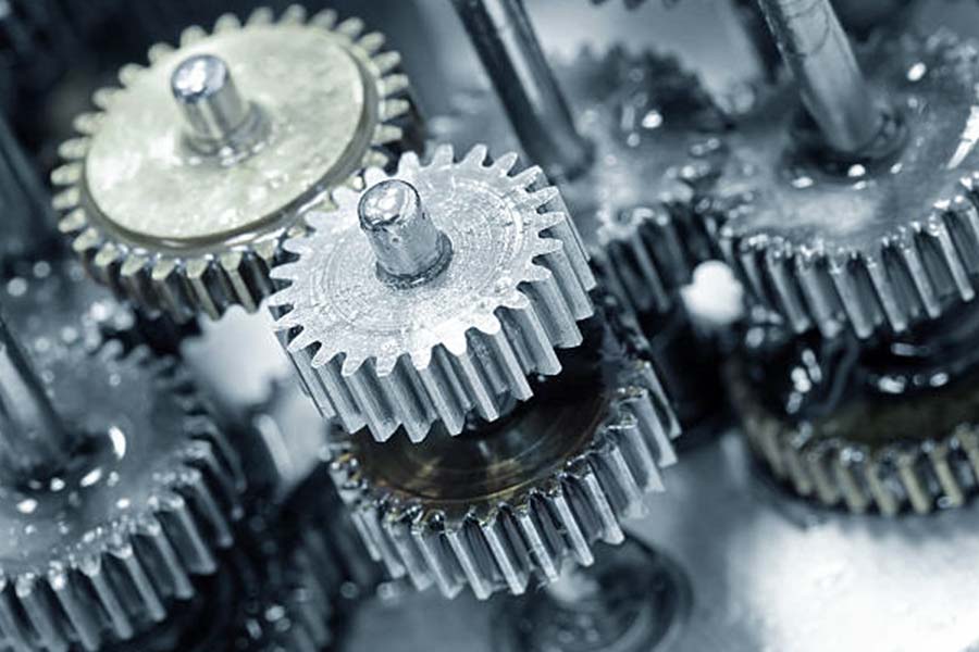
Have you ever wondered how pinions make machines move? These small gears may not look very good, but they play a very important role in machines. From cars to large factory equipment, these gears, which usually range from a few millimeters to tens of millimeters in diameter, are key parts for machine operation in many fields. Pinions are often made of strong metals such as steel or brass, or plastic if they need to be lighter.
Next, let me show you what pinions are and how to operate them, and how flexible pinions can perform a variety of tasks in different industries.

What is pinion machining?
In simple terms, a pinion is a small cylindrical wheel with teeth on it. It mainly does one thing in a machine, which is to drive or drive a larger gear to rotate. The large gear that is driven by it is usually called a large gear or ring gear. The teeth on the pinion are specially designed to fit tightly on the teeth of the large gear. Through this tight fit, the pinion can transfer the rotational force from one rotating part (we call it an axis) to another axis.
How it works:
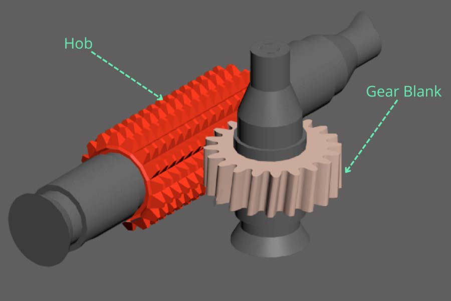
First, clamp a roughly shaped piece of metal material (gear blank) firmly on the machine's workbench or chuck to ensure that it does not move around.
The machine will rotate or move with very hard tools (such as turning tools, milling cutters, and hobs). These tools "gnaw" the excess material on the gear blank little by little according to the set path. This step is mainly to quickly remove most of the unnecessary metal and make the general outline of the pinions.
After rough processing, the gear is not precise and smooth enough. At this time, a finer tool will be used at a slower speed to finely cut or grind the surface of the gear teeth. This step is the most critical, the purpose is to make each tooth have the same shape, size, and angle, and the surface is very smooth, so as to ensure that the gear turns smoothly, quietly, and the power transmission is accurate.
After each tooth is processed by the machine, the gear blank will be rotated very accurately by a fixed angle (this process is called indexing), and then the next tooth will be processed.
After the pinions is processed, it cannot be used directly. Special tools must be used to carefully measure and check whether the size, shape, surface finish and distance between teeth of the pinions are in full compliance with the requirements of the drawings. Only gears that pass the inspection can be assembled and used.
What is the purpose of pinion machining?
The core purpose of pinion machining is actually very clear, which is to make a gear with precise size, perfect tooth shape, smooth surface, and strong and durable. Specifically, it is to achieve the following key points:
1. Accurate force transmission
The main job of the pinion is to work closely with another gear (large gear or rack) to transmit the power and movement of rotation exactly. Processing is to ensure that the shape, size, and angle of each tooth are made exactly right, so that they can smoothly and efficiently bite together to transmit force, avoiding slipping, jamming, or power loss.
2. Smooth rotation
If the gear stumbles or makes a harsh noise when it rotates, it will definitely not work. Precision machining can make the gear tooth surface very smooth, and the matching clearance between the teeth is just right. In this way, the gear can rotate smoothly and quietly at high speed, reduce vibration and wear, and make the entire machine run smoother and have a longer life.
3. Durable
pinions are under great pressure and friction when working. The processing (especially heat treatment and finishing) can make the pinion surface harder and more wear-resistant, and the internal structure tougher. In this way, it can withstand long-term, high-load operation, and is not easy to deform, wear too quickly or break suddenly.
4. Perfect match
Each pinion is not isolated, it is designed for a certain machine or equipment. The processing is to make it fully meet the requirements of the design drawings, whether it is the number of teeth, module (tooth size parameters), pressure angle or other dimensions. Only when it is processed perfectly can it be installed in the equipment tightly, work with other parts, and play its due function.
What are the common methods for machining pinion gears?
1. Gear hobbing
This is the most commonly used and efficient method at present. A tool (called a hob) with a shape similar to a worm or a toothed screw is used. It matches the tooth shape of the pinion gear being processed.
During processing, the hob rotates at high speed for cutting, and at the same time moves slowly along the width direction of the gear, and the rotation speeds of the two are strictly matched. The tooth shape of the hob will continuously cut out tooth grooves on the blank. This method is highly versatile and can process spur, helical and herringbone cylindrical gears with good accuracy and efficiency.
2. Gear shaping
This method is particularly suitable for processing internal gears (teeth on the inside of the ring) and multi-gears with multiple gears close together.
During processing, the pinion gear shaping cutter makes a rapid reciprocating motion up and down (cutting motion), and at the same time, the gear shaping cutter and the gear blank rotate at a certain speed ratio like a pair of meshing gears (this is called development motion). Each time the tool is inserted, it rotates a little, and the blank also rotates a little, bit by bit, and the tooth shape is gnawed out. The tool structure is relatively simple compared to gear hobbing.
3. Gear milling
It is similar to milling grooves with an ordinary milling machine. Use a disc milling cutter or a finger milling cutter with the same shape as the gear tooth groove. During processing, the pinion gear blank is fixed on a rotary table that can be indexed. The milling cutter rotates and cuts. After milling a tooth groove, it stops and rotates the gear blank by an angle of one tooth (indexing), and then processes the next tooth groove.
In this way, teeth are made one by one. This method is relatively simple and direct, and does not require complex gear-specific machine tools. It is particularly suitable for single-piece, small-batch production, repair or processing of very large-sized and large-module gears. But the disadvantage is low efficiency and relatively poor precision, because each tooth is processed separately, which is prone to cumulative errors.
4. Wire cutting
This method does not require contact cutting, and is particularly suitable for processing pinions that become very hard after quenching, or gears with complex shapes and thin sheets. A moving thin metal wire (electrode wire) is powered on to generate discharge sparks between the electrode wire and the gear blank. The high temperature of the electric spark ablates the metal little by little, and the gear profile is cut along the set gear profile.
It is a good choice for pinion gears with small batches, high hardness, and complex shapes. However, its processing speed will be relatively slow and the cost will be relatively high.
5. Powder metallurgy
This is a non-cutting forming process suitable for mass production of pinion gears with less complex structures. The mixed metal powder is placed in a mold that matches the shape of the gear, pressed into shape with great pressure, and then sent to a high-temperature furnace for sintering to turn the powder particles into solid gear parts.
This method can produce a complete tooth profile in one go, with extremely high efficiency and almost no waste. The precision and strength of the gears produced are usually not as high as those produced by cutting, and the complexity of the shape is also limited by the mold.
The following are the key capabilities of these processing methods:
| Processing | Typical applicable modulus (mm) | Typical tooth profile accuracy level (ISO) | Machinable gear types | Surface roughness Ra (μm) |
| Gear hobbing | 0.5 - 10+ | IT7-IT9 | External straight teeth, external oblique teeth, and external helical teeth. | 1.6 - 6.3 |
| Gear shaping | 0.5 - 8 | IT7-IT9 | Internal gear, multi gear, external spur gear, external helical gear. | 1.6 - 6.3 |
| Milling teeth | 1 - 20+ | IT9-IT11 | External straight teeth and external oblique teeth (limited). | 3.2 - 12.5 |
| Wire cutting | 0.2 - 5 | IT5-IT7 | Any shape of external/internal teeth (such as thin sheets, irregular shapes). | 0.8-1.6 (slow walking wire) |
| Powder metallurgy | 0.3 - 5 | IT8-IT11 | A relatively simple external straight/helical tooth structure. | 3.2-6.3 (sintered state) |
Description:
- Module (mm): The larger the value, the larger and stronger the teeth.
- Tooth profile accuracy grade (ISO): The smaller the IT value, the higher the accuracy, the smoother the gear transmission and the lower the noise.
- Surface roughness Ra (μm): The smaller the value, the smoother the surface, the lower the friction, and the longer the life.
Which industries often use pinion machining?
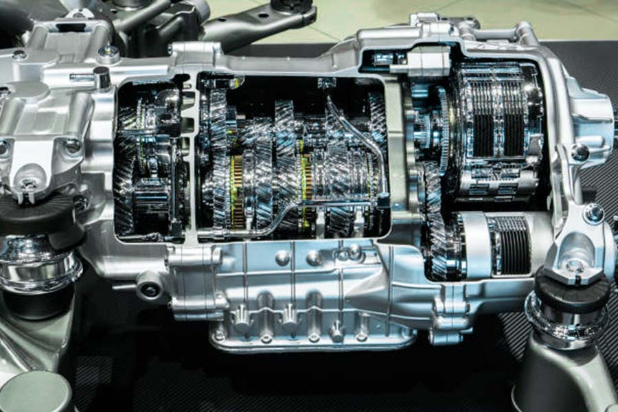
1. Automotive industry
- Differential: This is one of the "main battlegrounds" of pinion gears. As a car turns, the inner and outer wheels have to rotate at different rates. The ring gear and pinion in the differential synchronize to transfer power flexibly to allow the turn to be smooth and safe. Without it, it would be difficult for the car to turn.
- Steering system: Why does the power end up on the wheels when you rotate the steering wheel? It contains a pinion within, which directly translates the rotation of the steering wheel into a pulling translation of the wheels to move, and the feedback is immediate and direct.
- Gearbox: There are gears of varying sizes inside, but there are additional smaller gears that are needed as well, being careful to shift and transfer power between the alternative gears so that the automobile can move and stop, and the gear shifting is smooth.
2. Equipment for industry
- Machine tools: In the feed system and spindle drive of milling machines, machining centers, and lathes, miniature gears are responsible for controlling the speed and position of tools or workbenches with precision, and are behind-the-scenes heroes in ensuring machining accuracy.
- Robots: Much of the flexibility of robots' joints relies on highly precise pinion gear reducers (such as planetary gears and harmonic gears) to achieve high-precision motion, in order for the motions to be that smooth and precise.
- Various line production equipment: From food package equipment to printing equipment, if it is about timing, quantitative, and positioning movement or transmission, you can almost see pinion gears running quietly so that the production beat is never interrupted.
3. Aerospace
- Engines: Aircraft engines contain a great many gearboxes, and pinion gears are responsible for controlling accurately the torque and speed of large accessories such as generators and fuel pumps. There can be no mistakes, which has direct linkages to flight safety.
- In retraction and extension mechanism of landing gear, pinions are employed so that such a heavy piece of equipment may be extended and retracted smoothly and reliably and it should not loosen at critical moments.
- Flight control system: The action of controlling the control surfaces of the plane (ailerons, rudders, etc.) is normally expressed by pinions behind the scenes, and absolute accuracy and reliability are required. After all, it's a question of hundreds of lives.
4. Medical equipment:
This industry demands very exacting requirements on the accuracy, reliability and cleanliness of pinions. For example:
- Surgical equipment: Orthopedic surgical orthopedic procedure electric drills, tissue cutting or suturing staplers, etc., have precise pinions as their transmission nucleus.
- Diagnostic equipment: Large medical scanning machines such as CT and MRI scanning beds need smooth movements and lifting, and the robot arms of automated biochemical analyzers, which analyze samples, all rely on a reliable pinion transmission system.
- Dental equipment drives: Whether a dental drill rotating at high speed or position and height adjustment mechanism of a dental chair, they require accurate and durable gear drives.
- Pharmaceutical devices: In devices such as insulin pumps or infusion pumps where dosage of the drug is required to be very accurately controlled, the metering transmission mechanism of the inner core is generally composed of pinions high-precision gears.
How to choose equipment for pinion machining?
Here are some commonly used equipment for pinion machining:
| Device Type | Mainly processing tooth profiles | Typical applicable modulus range | Precision potential | Productivity | Suitable for batch production | Relative cost |
| Hobbing machine | Straight teeth and helical teeth. | Small and Medium Modulus. | Tall | Tall | Medium to large quantities. | Rising-falling |
| Gear shaping machine | Straight teeth, helical teeth, and internal teeth. | Small and Medium Modulus. | Tall | Rising-falling | Medium to large quantities. | Rising-falling |
| Gear milling machine (CNC) | Straight teeth, helical teeth, complex. | Wide range. | Rising-falling | Low to medium | Single piece small batch. | Centre |
| Gear shaving machine | Straight teeth and helical teeth. | Small and Medium Modulus. | Very high | Tall | Large scale precision machining. | Tall |
| Gear grinding machine | Various types of tooth shapes. | Wide range | Highest | Low | High precision small batch. | Very high |
| Car milling composite center |
Straight teeth and helical teeth (limited).
|
Small modulus. | Rising-falling | Rising-falling | Small and medium-sized batches. | Very high |
1. Clear requirements: Clearly list all the technical parameters of the pinion (tooth shape, module, accuracy, material, size) and production requirements (batch, efficiency).
2. Preliminary screening: According to the above table, exclude obviously unsuitable equipment types (such as milling is rarely selected for mass production, and high-precision hardened tooth surface usually requires grinding).
3. Accuracy and efficiency: On the premise of meeting the basic accuracy requirements, give priority to equipment that can meet the production cycle. Gear hobbing and gear shaping are usually the first choice for mass production.
4. Consideration of special requirements: If there are special structures such as internal teeth and shoulder teeth, gear shaping machines or specific CNC equipment may be necessary options. If ultra-high precision is required and the material can be grinded, gear grinding is the final solution.
5. Cost accounting: Comprehensively consider the equipment purchase cost, tool cost, operation and maintenance cost, labor cost and plant renovation cost.
6. Equipment inspection: For the 2-3 types of equipment selected, in-depth inspection of the performance parameters, reliability, technical support and services of specific brands and models.
How to deal with the challenges of pinion machining?
1. Control deformation
- Improper clamping of pinion is very easy to cause deformation. It is preferred to use a clamp that can provide uniform wrapping support, such as a collet or a custom soft-jaw chuck.
- JS generally inserts a mandrel of matching size into the inner hole of the gear before clamping to reduce clamping deformation.
- Note: The clamping force should be just right. Too little will cause looseness and vibration, and too much will directly crush or deform the gear.
2. Tool selection
- The tool for cutting pinions must be very hard and wear-resistant. We generally choose coated carbide tools as the first choice, which are much more powerful than ordinary high-speed steel tools and can withstand higher speeds and faster feeds.
- The tool tooth profile must be exactly consistent with the designed tooth profile, which is the basis for ensuring the final tooth profile accuracy.
- The blade must be sharp enough, so that cutting is labor-saving and less heat is generated, and it is not easy to deform the gear or burn the surface.
- Strictly implement tool life management and replace or regrind worn tools in time. Using worn tools will deteriorate surface quality, produce burrs, and seriously affect size and tooth profile accuracy.
3. Accurately set processing parameters
Ensure machine tool accuracy: Before processing, the radial runout of the tool rotation axis and fixture must be checked and adjusted to control it at the micron level (< 0.005 mm). The machine itself must also be stable to avoid processing vibration.
Cutting is done in two steps:
- First, rough machining, quickly remove most of the material, but leave a uniform and appropriate amount of allowance for finishing (for example, leave 0.2-0.3 mm).
- Then, finish machining, use high spindle speed, small feed per tooth, and small cutting depth to cut out the accuracy and finish little by little. This can reduce cutting force and heat.
Parameter optimization: The three parameters of speed (S), feed rate (F), and cutting depth (Ap) should be well matched. Higher speed, slower feed, and reduced cutting depth are usually good for accuracy and surface, but they should not be too extreme. It depends on the specific material and tool.
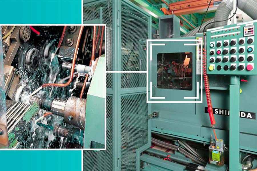
4. Manage cutting and lubrication
- It is difficult to dissipate heat in the processing area of the pinion, and the accumulation of cutting heat can easily cause workpiece deformation and accelerated tool wear.
- Adequate cooling and lubricating fluid must be provided and ensured that it is accurately and continuously sprayed into the cutting area. For finishing, oil-based cutting fluids usually provide better lubrication and surface quality.
- If conditions permit, high-pressure cooling can more effectively flush chips and reduce the temperature of the cutting area.
5. Consider material properties
Select gear materials with uniform texture and stable performance.
If the pinion needs to be heat treated after processing, the size and shape changes that may be caused by heat treatment must be foreseen.
Countermeasures include:
- Arrange heat treatment before final finishing, and perform finishing after heat treatment to correct deformation.
- During finishing, reserve a specific deformation compensation amount based on the material, heat treatment process and past experience.
Summary
pinion machining may seem like a small thing, but it is not easy to do well. It concentrates on all aspects of precision manufacturing. From the selection of tools, cutting methods or other special processing methods, to precision machine tools and equipment, each step requires deep professional knowledge and experience accumulation. Only by truly understanding how to process and where the key points of the process are, can we design and manufacture a gear transmission system that rotates steadily, is efficient and has low noise.
Our JS company focuses on this field. With solid process technology and advanced equipment, we are particularly good at handling the processing challenges of these precision pinions. For those extremely precise tiny gears, we can meet your stringent requirements.
Choosing JS is choosing a strong partner in precision manufacturing. Learn more about how we can provide reliable and efficient solutions for your pinion needs!

Disclaimer
The content of this page is for informational purposes only.JS Series No representations or warranties of any kind, express or implied, are made as to the accuracy,completeness or validity of the information. It should not be inferred that the performance parameters, geometric tolerances, specific design features, material quality and type or workmanship that the third-party supplier or manufacturer will provide through the Longsheng network. This is the responsibility of the buyerAsk for a quote for partsto determine the specific requirements for these parts.please Contact us Learn more information.
JS Team
JS is an industry-leading companyFocus on custom manufacturing solutions. With over 20 years of experience serving more than 5,000 customers, we focus on high precisionCNC machining,Sheet metal fabrication,3D printing,Injection molding,metal stamping,and other one-stop manufacturing services.
Our factory is equipped with more than 100 state-of-the-art 5-axis machining centers and is ISO 9001:2015 certified. We provide fast,efficient and high-quality manufacturing solutions to customers in more than 150 countries around the world. Whether it’s low-volume production or mass customization,we can meet your needs with the fastest delivery within 24 hours. choose JS Technology It means choosing efficiency, quality and professionalism.
To learn more, please visit our website:jsrpm.com
FAQs
1. What is the role of pinion in machinery?
The core role of pinion in machinery is to transmit power and change the form of motion (such as speed, torque, direction). It is usually used as a driving wheel to mesh with large gears to drive the system.
2. What materials are used in the manufacture of pinion?
High-strength steel (such as 20CrMnTi), alloy steel, stainless steel, cast iron and engineering plastics (such as nylon). The specific choice depends on strength, wear resistance, corrosion resistance and working conditions.
3. What machine tools are commonly used to process pinion?
Gear hobbing machine (most mainstream), gear shaping machine, CNC milling machine/machining center, gear grinding machine for fine processing when high precision is required.
4. Why is pinion processing so important to precision industry?
The high precision of pinion processing directly determines the efficiency, noise control and life of the transmission system. It is the core guarantee of power transmission of high-end equipment such as industrial mother machines, aerospace, etc. Insufficient precision will lead to system failure.
Resource