In the manufacturing industry, precision, production speed, and quality control of products are all key. At this point, CNC turning (Computer Numerical Control Turning) came into great use -- this technology can efficiently cut materials while ensuring high precision.
Nowadays, it can be seen in the production of automotive parts, aircraft components, and even medical equipment. If you are curious about how machines turn a piece of metal into complex parts, or want to learn the secrets of automated production, this article will take you through how CNC turning works and the challenges it faces.

What is CNC turning?
Simply put, CNC turning is the process of gradually removing excess parts using rotating raw materials and precisely controlled cutting tools, ultimately achieving the desired shape of CNC turning parts. The CNC here actually represents computer numerical control, which allows computer programs to fully command the machine tool to work.
Unlike old-fashioned lathes, lathes are completely controlled by pre programmed CNC turning program (such as commonly used G-code), which can not only automatically switch tools, but also accurately machine complex structures such as cylinders and threads, and even control errors within 0.01 millimeters!
What is the function of CNC turning service?
In layman's terms, CNC turning service refers to the use of computer-controlled machines to "shape" metal materials, such as automotive parts and screws that require rotational processing, all of which are completed by it. The biggest advantage of this technology is that it can minimize manual operation errors, with an accuracy of one tenth of a human hair, and can also rotate continuously for 24 hours, making it particularly suitable for large-scale production.
Nowadays, many processing plants use a combination of CNC turning & milling to ensure accuracy and improve efficiency. Especially for the popular small batch custom orders nowadays, this flexible production method is particularly popular. Customers need a special-shaped joint today and a grooved shaft tomorrow, and the CNC equipment can quickly adjust the program to handle it.
In fact, the core function of CNC turning services is to make metal processing smarter and more reliable. It not only retains the basic principles of traditional mechanical processing, but also adds the advantages of intelligent control. When combined with CNC milling, it can basically meet more than 80% of the parts processing needs in the manufacturing industry.
How does CNC turning generally work?
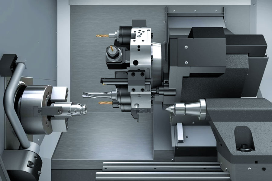
Usually the first step is to clamp the metal bar (most of the time it is round) on the chuck of the lathe. This chuck is like an electric gyroscope that can rotate with the material. At this time, the cutter head fixed on the tool holder starts to work. It slowly approaches the rotating material according to the preset route and cuts off the excess part layer by layer.
So how does the machine know where to cut? The key lies in the CNC turning drawing PDF design file we provide. It's like you give our engineers a drawing. We convert the CAD three-dimensional design drawing or CAM processing instructions into a language that the machine can understand. The workshop master personally performs CNC turning programming.
This system is like installing a master who can't shake his hands on the machine. Every millimeter of the route that the cutter head takes is calculated in advance. Not to mention making ten or eight, even making a thousand parts can ensure that each one looks like a twin.
The entire processing process is actually a combination of rotation + cutting. The faster the material rotates, the more precise the movement route of the cutter head, and the closer the final part is to the requirements of the design drawing. Many processing plants now like to use this method, especially for parts that need to be processed in a circle, such as the piston rods in the engine or the precision shafts on medical equipment. It can not only ensure the size is accurate to the millimeter, but also improve production efficiency.
What parts does a CNC lathe consist of?
A CNC lathe is like a division of labor robot squad, and each member has its role. Let's divide it from the 7 most essential parts:
1.Command center -- control unit
It is like the brain of the lathe. As soon as the operator puts in the command, it is able to translate the command of "screw-turning" into machine-readable language and tell each component to work together with precision. It's like installing an automatic driving system on the lathe.
2.Power heart -- spindle system
- Spindle: Spin chuck and workpiece wildly, its top speed is 6000 revolutions per minute (3 times that of an electric drill).
- Sub-spindle: The "second pair of hands" available only in high-end models can be driven automatically to the back of the workpiece for further treatment. For making double-headed screws, after turning the thread on the front, the sub-spindle retains the workpiece and turns it over to continue turning, eliminating the discomfort of re-clamping.
3.Machinery palm -- chuck & collet
- Chuck: Steel pincers three strong fingers of iron hold the workpiece, and can clamp an as-large-as-a-washbasin steel block.
- Collet: Particularly small parts, like an electric drill's drill chuck, suitable for machining precision-sized parts the size of a keychain.
- Our little secret: It is recommended to use a chuck to machine components of a diameter less than 6 cm, which give a tighter grasp.
4.Steel backbone -- lathe bed
The heavy cast iron foundation is the lathe's equivalent of the "skeleton." It must withstand the vibration of high-speed revolution and stabilize the turret from swerving when it travels, imagine embroidering on a moving bus, relying on this mass of iron to stabilize the scene.
5.Turret system
- Turret: 12-20 different tools are supported to be mounted on the circular turntable, and turning tools, drill bits, and threading tools are arranged in line.
- Tool changing black technology: It automatically switches to the target tool with a program command within 0.5 seconds, 10 times faster than the old master finding the tool.
- Tool holder: All tools have their own position, it can precisely set tool extension length (accuracy to 0.01mm) with adjustment screws.
6.Cutting tools
Material selection:
- Diamond-coated tools: For soft metals like aluminum, they can cut continuously at high efficiency and low resistance.
- Carbide tools: Fortified with the addition of elements like cobalt and titanium, they are applicable to stable processing of high-hardness materials like stainless steel and titanium alloys.
Structural features:
- Thread cutters: They can cut standard metric/imperial threads with precisely aligned cutting teeth.
- Cut-off tools: Extremely narrow tool body construction (thickness of tool body 3-6mm) is used for delicate separation of workpieces.
- Inner hole tools: Thin shaft is combined with a micro-cutting head, and the minimum cavity structure that can be machined is Φ2mm.
Processing strategy:
- Roughing stage: Use high rake angle cutters to quickly take out more than 90% of the allowance, and the cutting depth can be as much as 5mm.
- Finishing stage: Switch to small radius tool (R0.2-0.4mm), reduce feed speed to 0.05mm/r, and obtain Ra0.8μm surface.
7.Cooling system
Although not included, cutting fluid injection is very important:
- Cool the tool (the tip temperature is over 500℃ in high-speed cutting).
- Flush away iron chips to prevent tool entanglement.
- Execute "polishing SPA" on the surface of machining.

How to set CNC turning center parameters?
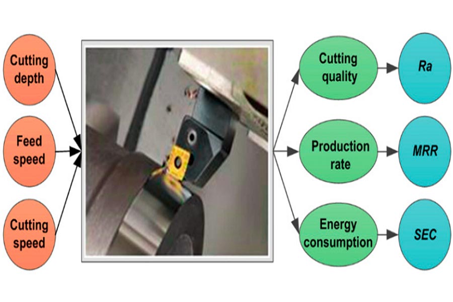
In actual processing of CNC turning machines, the following four fundamental parameters must be regulated by operators in terms of specific working conditions. These parameters have a direct impact on processing efficiency, tool life and quality of final products:
1.Spindle speed (rpm)
The spindle speed and workpiece diameter are inversely proportional, much like when decreasing the revolution speed to mark a big circle with a compass. As the diameter increases, the speed must be reduced in an effort to maintain constant cutting line speed.
2.Feed rate (mm/rev)
The per-revolution travel of the tool has a direct correlation with surface finish and machining productivity:
- Too high: results in tool jumping or workpiece surface damage.
- Too low: Longer processing time and prone to burrs.
Recommended benchmark value:
Steel: 0.1-0.3 mm/rev.
Aluminum material: 0.2-0.5 mm/rev.
3.Impact of workpiece diameter
Diameter size has a direct influence on two critical factors:
- Tool selection: For diameters >50mm, a reinforced tool holder is recommended.
- System stiffness: When the diameter <20mm, feed rate can be reduced in order to prevent vibration.
4.Cutting depth (mm)
Key areas for controlling the amount of material taken out per operation:
- Rough machining: to the edge of cutting tools (hard alloy knives: 1.5mm for steel components, 3mm for aluminum components).
- Precision machining: controlled in 0.1-0.5mm (depending on surface roughness requirement).
| Abnormal condition | Adjustment scheme |
| Tool wear | Depth reduction of 0.2-0.3mm. |
| Interrupted cut | Depth reduced to 50% of the normal value. |
| The material contains hard spots | Depth ≤ 0.5mm. |
JS special reminder: When processing stainless steel, the depth should be reduced by 20% to avoid tool breakage.
What are the key considerations in CNC turning programming?
1.Material characteristic identification
(1)Correspondence between materials and tools:
- Soft materials: Such as aluminum alloys, diamond-coated tools are preferred, which have a friction coefficient 40% lower than that of ordinary tools and can achieve smooth continuous cutting.
- Hard materials: When processing hardened steel (HRC>50), CBN (cubic boron nitride) blades must be used, whose high temperature resistance can withstand a cutting temperature of 1200°C.
(2)Preventive measures for abnormal processing:
- Stainless steel sticking: Increase the concentration of water-based coolant to 8%-10%, and add extreme pressure additives to avoid chip melting.
- Cast iron dust control: Use blades with rake angle chip breakers, and use a 2.5m/s gas purge system to clean the work area in real time.
- Typical case: When a workshop processed 304 stainless steel sleeves, the Q parameter of the G75 command was not enabled, resulting in 3mm wide chips wrapped around the spindle, causing the equipment to stop suddenly. After the Q value was adjusted to 0.3mm, the chip length was controlled within 15mm, and the processing continuity was significantly improved.
2.Geometric structure processing
(1)Disassemble complex parts into three steps:
① First turn the outer circle.
② Then flatten the end face.
③ Finally dig the groove (pay attention to the retraction space).
(2)Anti-collision checklist:
- Tool bar length: When processing deep holes, the total length of the tool bar should be less than 4 times the hole diameter (for example, when processing a Φ20mm hole, the tool bar is up to 80mm).
- Clamp clearance: Leave at least 3mm safety distance, imagine it as the distance between the front and rear vehicles when parking.
- Special shape: When encountering an inner concave arc, a tool with an R angle less than the contour radius must be used.
(3)Remaining allocation strategy:
- Critical mating surfaces (such as bearing points): Leave a finishing allowance of 0.02mm, which is 1/4 of the thickness of a hair.
- Non-critical parts (such as process bosses): May be relaxed to 0.1mm, saving around 30% of the processing time.
- Deformable parts: Process in steps, first leave 0.5mm allowance and fine-turn subsequently after aging treatment.
(4)Three things are required to be done when debugging the program:
- Empty run check: Test run at 200% feed rate on the machine tool, observing to note down the tool change point.
- First piece measurement: After machining the first component, use three coordinates to measure 3 key sizes.
- Adjustment of parameters: Adjust according to actual cutting sound, normal cutting sound should be as flat as tearing paper.
3.Tool path planning
| Path Type | Spiral cutting applicable scenarios | Advantages | Risks |
| Contour cutting |
Step shaft machining.
|
Reduces idle travel. | Corners are prone to overcutting. |
| Spiral cutting in | End face turning. | Reduces impact force. | High programming complexity. |
| Copy tracking | Special-shaped contour. | High precision. | Time consumption increased by 40%. |
4.Cutting parameter linkage
- Balance of three elements: speed (n), feed (f), and cutting depth (ap) need to be adjusted dynamically.
- Roughing formula: ap (3mm) × f (0.3mm/r) = high material removal rate.
- Finishing formula: n (2,000rpm) × f (0.05mm/r) = high surface quality.
- Machine tool load monitoring: automatic speed reduction when power exceeds 85% of the rated value.
5.Three principles of fixture positioning
- Consistent datum: From design drawings to processing and clamping to quality inspection, the same set of positioning datum points must be used to avoid error relay.
- Rigidity guarantee: When processing slender parts (such as hydraulic rods) with a length exceeding 5 times the diameter, a follower tool holder must be installed to prevent bending and deformation.
- Fast changeover: Using a quick-change fixture system, positioning modules are combined like Lego blocks, and the production change time is compressed from 2 hours to 40 minutes.
6.Three tricks for program optimization
- Rough turning cycle: Use G71 command to package and process repeated cutting steps, and directly cut the amount of code by 70%.
- Intelligent tool compensation: In the T0101 number, the first two digits select the tool, and the last two digits 01 represent the compensation value of tool No. 1, which corrects the wear error at any time.
- Subroutine reuse: When encountering the same structure, use M98 to call the written program segment to save the need to type code repeatedly.
7.Quality and safety control
Online detection: Insert M05 spindle stop command in the program and automatically compensate the size with the probe.
Emergency plan:
X/Z axis soft limit setting to prevent machine collision.
Set the maximum cutting load for each tool separately.
Breakpoint continuation processing: Quickly locate the interruption position through line number retrieval.
Challenges faced by CNC turning and how to solve them?
Challenge 1: Difficulties in processing hard materials
Typical problem: When processing hardened steel (HRC55 or above) and high-temperature alloys, the tool wear rate increases by 3-5 times, and the surface roughness is difficult to control.
Solution:
- We use CBN (cubic boron nitride) tools with a heat resistance of up to 1200℃, combined with high-pressure cooling (pressure ≥7MPa).
- Implement variable parameter processing: the line speed is 80m/min in the rough processing stage and reduced to 50m/min in the fine processing stage.
- Introducing ultrasonic vibration assisted turning technology, the cutting force is reduced by 40%.
Application case:JS increased the tool life from 15 pieces/blade to 45 pieces/blade through the above solution when processing Inconel 718 turbine disks.
Challenge 2: Complex structure processing
Typical problem: For structural parts with inner cavity cross holes, the tool path is prone to interference (for example, when processing aerospace joint parts, the distance between the tool bar and the inner wall is <1mm).
Preventive measures:
During the programming phase, our engineers use 3D simulation software to detect the path, focusing on:
✓ Tool change point position.
✓ Arc cutting in and out angles.
✓ Tool holder swing space.
Three-step verification before actual processing:
① Observe the machine tool motion trajectory by running with an empty tool
② Test cutting with a nylon test piece
③ Reduce the feed speed by 50% when processing the first piece
Challenge 3: The contradiction between processing efficiency and quality
| Parameter combination | Takt time | Surface roughness Ra | Tool cost per piece |
| Conventional cutting | 25min | 1.6μm | $8.5 |
| High-speed turning | 18min | 0.8μm | $6.2 |
| Hard dry turning | 12min | 0.4μm | $4.8 |
Breakthrough path:
- Use PCBN tools to implement hard turning instead of grinding (saving 60% of process time).
- Develop an adaptive feed system to dynamically adjust parameters according to the cutting load.
- Apply composite processing technology, CNC turning and milling center integrates milling function.
Summary
With its high-precision and high-efficiency machining function, CNC turning technology has become the preferred choice to manufacture cylindrical components. From shaft parts of precision for engine application in vehicles to internal cavity structure with millimeter dimensions in medical products, advanced configurations such as power tool libraries and multi axis linkage enable a machine to execute the whole process of complex part machining.
If your parts are to be customized, JS's digital manufacturing platform provides you with solution from turning to milling. Simply upload the design drawings online, and we will provide you with free manufacturability analysis, from material selection to tolerance optimization. You can get into the manufacturing process within as few as 48 hours. Upload your 3D model and experience our smart manufacturing service of turning drawings into parts today!

Disclaimer
The content of this page is for informational purposes only.JS Series No representations or warranties of any kind, express or implied, are made as to the accuracy,completeness or validity of the information. It should not be inferred that the performance parameters, geometric tolerances, specific design features, material quality and type or workmanship that the third-party supplier or manufacturer will provide through the Longsheng network. This is the responsibility of the buyerAsk for a quote for partsto determine the specific requirements for these parts.please Contact us Learn more information.
JS Team
JS is an industry-leading companyFocus on custom manufacturing solutions. With over 20 years of experience serving more than 5,000 customers, we focus on high precisionCNC machining,Sheet metal fabrication,3D printing,Injection molding,metal stamping,and other one-stop manufacturing services.
Our factory is equipped with more than 100 state-of-the-art 5-axis machining centers and is ISO 9001:2015 certified. We provide fast,efficient and high-quality manufacturing solutions to customers in more than 150 countries around the world. Whether it’s low-volume production or mass customization,we can meet your needs with the fastest delivery within 24 hours. choose JS Technology It means choosing efficiency, quality and professionalism.
To learn more, please visit our website:jsrpm.com
FAQs
1.What is the role of the spindle in turning?
The spindle is the core component that drives the rotation of the workpiece, responsible for clamping the workpiece and transmitting rotational power. By precisely controlling the speed (50-3000 revolutions per minute), it ensures stable relative motion between the cutting tool and the workpiece, directly affecting machining accuracy and surface quality.
2.What is the core equipment of CNC turning?
A CNC lathe is a core equipment consisting of a numerical control system, spindle, and feed system. The CNC system parses program instructions, the spindle drives the workpiece to rotate, and the feed system controls the tool to move in a straight line. The three work together to complete precision cutting.
3.How does the tool move along the workpiece?
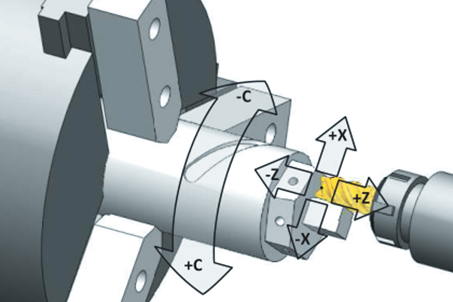
The cutting tool is driven by a servo motor to move precisely along the X-axis (radial) and Z-axis (axial). The CNC system controls the movement speed and path according to program instructions, and follows the set trajectory with a precision of 0.001mm during cutting to achieve complex contour machining.
4.What is the practical function of coolant?
Coolant mainly serves the functions of cooling, lubrication, and chip removal. It can take away 75% of cutting heat, prevent tool overheating (>600℃ will burn), wash iron filings to avoid tool entanglement, lubricate and extend tool life by more than 30%, and prevent workpiece thermal deformation.
Resource