In the industry of manufacturing, CNC milling technology is widely used in processing various complex parts due to its high precision and high efficiency. Whether in aerospace precision parts or automotive manufacturing critical parts, CNC milling cannot be substituted. However, in order to achieve high-quality CNC milling, some important design and engineering aspects need to be considered. The following factors will be explained in depth in this paper so that readers can have a better understanding of CNC milling technology and improve processing quality and efficiency.
What is CNC Milling?
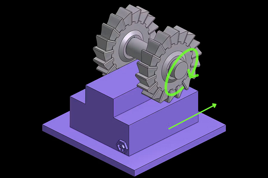
CNC milling (Computer Numerical Control Milling) refers to computer-controlled precision machining technology. By using a rotating tool, the workpiece is removed and raw materials (e.g., metal, plastic or composite materials) are machined into parts with complex geometric shapes. In contrast to traditional manual milling machines, CNC milling is exclusively controlled by computer instructions (G code), has sub-micron accuracy (usually as high as ±0.005mm) and high repeatability, and is the pivot of manufacture during the era of Industry 4.0.
What Are the Most Crucial Design and Engineering Aspects in CNC Milling?
The most crucial design and engineering aspects in CNC milling involve several key links, and comprehensive optimization is necessary to achieve efficient and accurate processing. The following is a list and explanation of the most crucial aspects:
1. Tool design and selection
Tool type matching
Choose a ball end cutter (complex curved surface), end mill (plane/groove machining) or circular blade (difficult-to-machine materials) according to the machining needs.
- Example: To machine an aircraft engine blade curved surface, a high-precision ball end cutter is required; machining titanium alloy requires high-temperature resistant carbide tools.
Geometric parameter optimization
- Main rake angle: affects cutting force distribution (e.g., 45° main rake angle radial and axial forces balanced, for face milling; 10° main rake angle for machining at high feed rate).
- Helix angle: Large helix angle (e.g., 45°) can reduce cutting vibration, but needs to be adjusted to the machine tool rigidity.
- Rake angle and back angle: Increasing the rake angle reduces cutting force but reduces the blade's strength; the back angle needs to be adjusted according to material hardness (hard material reduces the back angle for better support).
Coating and materials
The wear resistance of tools can be enhanced by coating technology (e.g., TiAlN, TiCN); ceramic or CBN tools can be applied in high-speed cutting of high-hardness materials.
2. Cutting parameter optimization
Balance of three factors
- Cutting speed: needs to be adjusted according to material properties (aluminum alloy can be as high as 1000m/min, titanium alloy has to be restricted to less than 60m/min).
- Feed rate: relates to chip thickness, thin chip (e.g. 0.1mm) can enhance feed rate, but tool strength should be ensured.
- Cutting depth: layered machining can remove vibration, e.g., the single cutting depth in roughing cannot exceed 50% of the tool diameter.
Path planning
Use arc cutting to reduce stress concentration; slow down at corners to avoid tool breakage.
- Example: In mold machining, use spiral cutting instead of vertical cutting to reduce impact.
3. Fixture design and workpiece clamping
Stability and rigidity
Avoid excessive tool overhang (recommended overhang/diameter ratio ≤3:1), and use vibration-damping toolholders as needed.
Example: When machining long thin shafts, support with a follower rest or center rest.
Positioning accuracy
Specialized fixtures can reduce the times of clamping (e.g., five-axis machining zero-point positioning system) and improve the positioning repeatability to ±0.005mm.
Thermal deformation control
When machining large workpieces, thermal expansion allowance should be reserved or low-temperature machining technology should be applied.
4. Vibration and thermal management
Vibration suppression
Optimization of cutting parameters (e.g., minimization of radial cutting depth), use of unequal pitch milling cutters or active vibration reduction systems.
- Example: When machining thin-walled parts, fill the workpiece interior with vibration-absorbing material.
Thermal error compensation
Monitor the thermal deformation of the machine tool through temperature sensors and compensate for the errors through CAM software.
5. Surface quality and precision
Surface roughness control
Tool sharpness (e.g., cutting edge radius ≤ 10μm), cutting speed (high-speed machining can reduce built-up edge) and cooling strategy (e.g., micro-lubrication MQL) all affect the surface quality.
Multi-axis linkage precision
In five-axis machining, simulation must be used to avoid tool collision with the workpiece, and RTCP (rotating tool center point) function is used to achieve higher precision.
6. Trade-off between efficiency and cost
Metal removal rate optimization
The efficiency can be improved by the "HSM (high speed milling)" strategy of large cutting depth and small feed, but machine power must be coordinated.
Tool life management
The tool wear monitoring system is applied, combined with CAM software tool path optimization, to extend the tool life by more than 30%.
7. Material adaptability
Machining of difficult-to-cut materials
- Titanium alloy: requires low-speed and high-pressure cooling cutting;
- Composite materials: PCD (polycrystalline diamond) tools are utilized to avoid delamination.
The main design of CNC milling must take into account the overall optimization of tool-process-workpiece-machine tool coordination. Through the scientific selection of tools, precise matching of cutting parameters, reinforcement of vibration and thermal control, and prevention of dangers in advance through simulation technology, the processing efficiency and quality can be greatly enhanced. In actual use, targeted process plans should be developed according to specific materials, precision requirements, and cost goals.
How to choose the proper main angle of milling cutter?
Choosing the main deflection angle of the milling cutter has a direct effect on the cutting force distribution, the life of the tool, the efficiency and surface quality of the processing in CNC milling. The following is the step-by-step analysis of the strategy of choosing the main deflection angle from material properties, processing requirement, tool type and process condition:
Choose as per the properties of the processed material:
- Softer materials (such as aluminum alloy and copper): Choose a primary angle of 45 ° to 60 ° for balancing the cutting force and efficiency.
- Hard materials (such as quenched steel and titanium alloys): Choose a primary angle of 10 ° to 25 ° to distribute the cutting force and reduce tool wear.
- Brittle materials (cast iron and ceramics): Choose a principal angle of 75 ° to 90 ° such that cracking is avoided.
Choose according to processing requirements:
- Rough machining (max. material removal): Choose the principal angle of 30 ° to 45 ° such that the cutting thickness is maximized.
- Precision machining (high surface finish): Choose the principal angle of 60 ° to 90 ° such that vibration is minimized and smoothness is enhanced.
- Thin walled pieces/slim shaft machining: Use the primary deviation angle of 75 ° to 90 ° to minimize the chance of deformation.
Pick based on cutting tool type:
- Face milling cutter: 45 °~60 ° for roughing and 90 ° for precise machining.
- End mill: 10 °~30 ° for roughing and 45 ° for general-purpose machining.
- Ball head knife: The main departure angle actively varies with the contact point of the curved surface, requiring CAM path optimization.
Select according to the process condition:
- High speed machining (HSM): Choose a main angle between 10 ° and 30 ° with high speed and shallow depth of cut.
- Intermittent cutting (e.g., keyway): Choose a main angle between 45 ° and 60 ° for a maximum impact toughness.
- Core principle: Small main deviation angle (10 °~30 °) is suitable for high hardness materials or efficient processing; Large main deviation angle (75 °~90 °) is suitable for brittle materials or thin-walled parts; Balance universality and efficiency with a moderate main deviation angle (45 °~60 °).
How to avoid overcutting of workpiece?
Overcutting is a common quality problem in CNC Milling, which may lead to scrapped workpieces, increased costs, and even equipment damage. The following is a systematic solution covering the entire process of design, programming, machining, and testing:
1.Programming phase
Path optimization
Simulate using CAM software (such as Vericut) to avoid abrupt changes in straight line segments and sharp transitions in circular arcs.
Set up a "safety plane" and "tool return path" to prevent accidental cutting of the tool.
Tool compensation
Correctly use G41/G42 compensation, dynamically adjust wear values, and avoid compensation errors.
Surplus and Stratification
Leave a margin of 0.1-0.3mm for rough machining, and reduce the depth of a single cut in layered cutting (such as contour milling).
2.Tools and fixtures
Tool selection
Prioritize short cutting tools (overhang/diameter ratio ≤ 3:1), with diameter adapted to machining characteristics.
Anti interference design
Simulate the spatial position between the fixture and the tool during five axis machining, and design the avoidance groove for the fixture.
3.Machine Tool and Operation
Accuracy Calibration
Regularly check the geometric errors of the machine tool and compensate for the reverse clearance.
Optimization
Reduce speed by 50% when cutting in/out to minimize impact; Avoid cutting with empty tools.
Real time monitoring
Monitor cutting force (power/vibration sensor) and shut down in case of abnormalities.
4.Detection and post-processing
First article verification
CMM full-size inspection+rapid calibration benchmark for on machine probes.
Surface inspection
Visual/microscopic confirmation of no cutting marks, CT scan (high-precision workpiece).
5.Typical Scenarios and Responses
| Scenario | Overcutting Cause | Solution |
|---|---|---|
| Thin-walled parts processing | Tool vibration causes path deviation | Use short tool + vibration-damping toolholder, layered cutting, single cutting depth ≤ 0.5mm |
| Five-axis linkage processing | Fixture and tool spatial interference | Use CAM software to simulate the motion trajectory and adjust the fixture structure or tool path |
| Deep cavity processing | Tool overhang is too long, causing bending | Use "spiral cutting" instead of vertical cutting, or use extension rod + guide sleeve |
| Curved surface processing | Tool radius compensation value is wrong | Verify the compensation value through trial cutting before processing, and establish a tool wear compensation database |
To avoid overcutting of workpieces, system control is required from five dimensions: programming path design, tool fixture optimization, machine tool accuracy assurance, real-time monitoring and detection feedback. The core principles include:
- Prevention first: discover risks in advance through simulation and trial cutting;
- Dynamic adjustment: optimize parameters in real time according to tool wear and workpiece material;
- Closed-loop verification: continuously improve the process based on detection data.
Through the above measures, the risk of overcutting can be reduced to less than 0.1%, significantly improving the processing yield rate.

What are the basic rules of CNC milling design?
The basic rules of CNC milling design mainly include the following aspects:
Tool accessibility
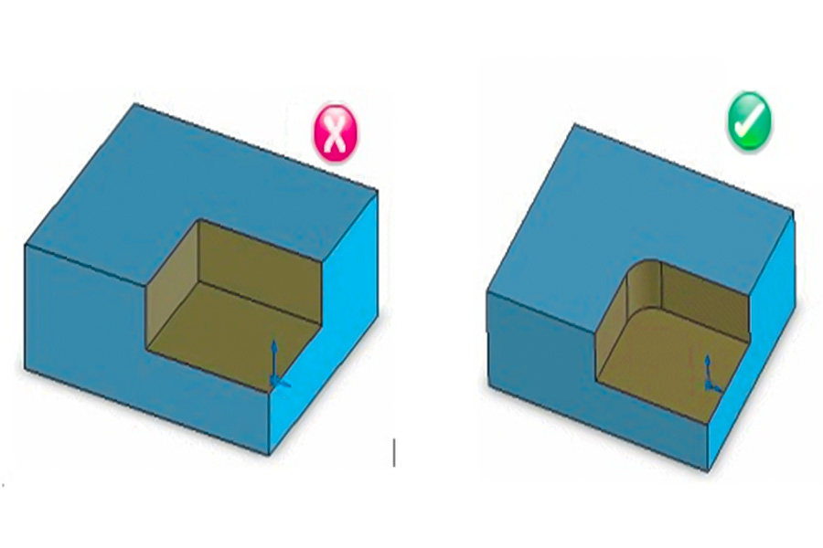
The cutting tool is cylindrical, and the inner corners should be designed with rounded corners (≥ 130% of the tool radius) to avoid right angles.
Deep cavity machining requires controlling the aspect ratio (recommended depth ≤ 4 times width), with a tool diameter to depth ratio of ≥ 1:6 (special tools can reach 30:1).
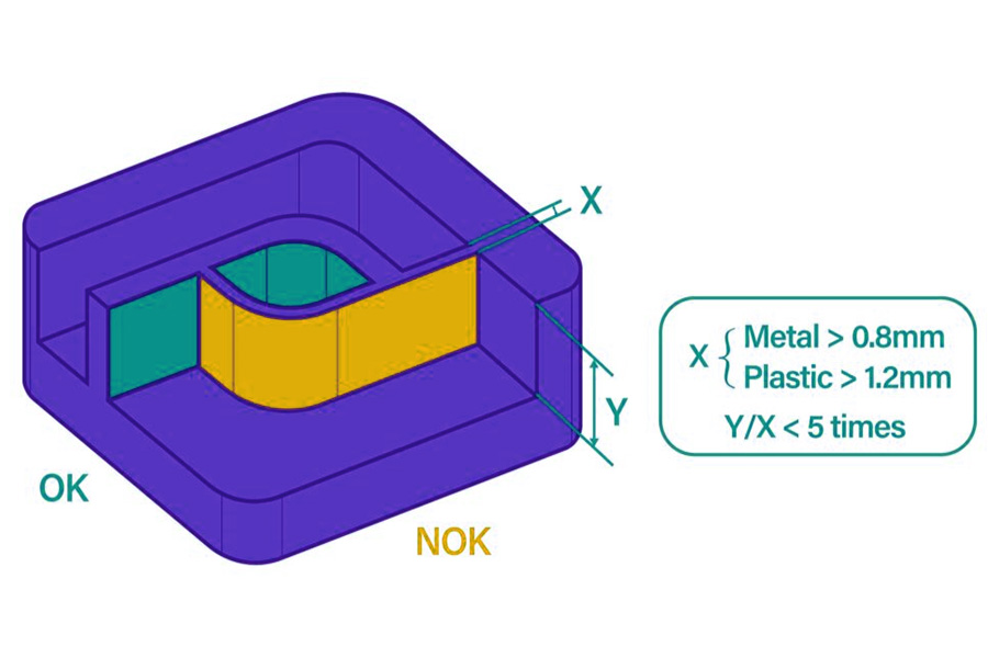
Wall thickness design
The minimum wall thickness for metal parts is ≥ 0.8mm, and for plastic parts it is ≥ 1.5mm. Thin parts are prone to vibration deformation.
Hole and thread design
Hole diameter ≥ 2.5mm, recommended depth to diameter ratio ≤ 4 times (typical 10 times, limit 40 times).
Thread length ≤ 3 times the aperture, leaving no threaded section at the bottom of blind hole threads.
Small features and tolerances
Special tools are required for microfabrication (aperture<2.5mm).
Tolerance grading: standard ± 0.125mm, typical ± 0.025mm, limit ± 0.0125mm.
Processing strategy
Cutting path: Arc cutting replaces straight cutting, with priority given to forward milling (reducing cutting force and heat).
Strategy selection: High speed machining is used for soft materials, and strong cutting is used for hard materials.
Matching materials and cutting tools
Tool materials are suitable for workpieces (such as PCD for aluminum alloys and CBN for quenched steel).
The cutting parameters (speed, feed, depth) need to be matched with the tool and material.
Clamping and tool optimization
Reduce the number of clamping times and complete the tight tolerance feature in a single clamping.
Limit the number of cutting tools (such as uniform aperture size) to reduce tool replacement costs.
Core principles:
- Machinability first: the design must meet the physical limitations of the tool.
- Balance precision and cost: optimize efficiency through tolerance grading and strategy selection.
- Reduce tool changes and clamping: reduce auxiliary time and improve processing consistency.
What are the effects of tool geometry in CNC milling design?
The main effects of tool geometry in CNC milling design are:
Lead Angle
Angle range: 45 ° (rough machining) to 90 ° (precision machining).
Effect: Small angle (45 °) increases axial force, is suitable for low rigidity machine tools; Large angle (90 °) reduces radial force, reduces vibration, and improves surface quality (Ra can be 0.4 μ m).
Anterior angle
Positive rake angle (+10 °~+15 °): light and easy cutting, easy chip discharge, suitable for soft materials such as aluminum and copper (20% increase in cutting speed).
Negative rake angle (-5 °~0 °): enhances blade strength, suitable for hard materials such as quenched steel and titanium alloys, and extends the tool life by 30%.
Relief angle
Normal value: 6 °~12 °.
Influence: If the back angle is too small (<6 °), it will raise friction and result in overheating; Too high back angle (>15 °) reduces the strength of the cutting edge and makes it susceptible to chipping (back angle for hard alloy cutting tools is recommended at 8 °).
Number of blades and helix angle
Number of blades: 2 blades (good chip evacuation, appropriate for deep groove machining); 4 blades (high stability, surface quality Ra ≤ 0.8 μ m).
Spiral angle: 30 °~45 ° (normal), high spiral angle (for example, 45 °) improves chip removal rate and reduces cutting temperature by 20%.
Nose radius
Rough machining: large radius (R0.8~1.2mm), good impact resistance, and raises feed rate by 15%.
Precision machining: small radius (R0.2~0.4mm), reduces cutting residue, and attains contour accuracy of ± 0.01mm.
Blade inclination angle
Positive blade angle (+5°): guides chips off machining surface to avoid scratches (generally used in machining stainless steel).
Negative blade angle (-5°): enhances strength of blade, usable in intermittent cutting (for example, cast iron).
The geometric form of the cutting tool controls the cutting force division (radial/axial force ratio), the surface finish (Ra value), tool durability (wear rate), the efficiency of the machining process (material removal rate), and vibration management. The combinations of parameters have to be dynamically optimized based on material hardness (e.g., aluminum/titanium), machining stage (coarse/fine), and machine tool stiffness.
In what ways is CNC milling distinct from CNC turning?
The following table is a comparison table of the basic distinction between CNC turning and CNC milling:
| Comparison dimensions | CNC milling | CNC turning |
|---|---|---|
| Processing type | Cutting a fixed workpiece by rotating the tool (subtractive processing) | Cutting a fixed/moving tool by rotating the workpiece (subtractive processing) |
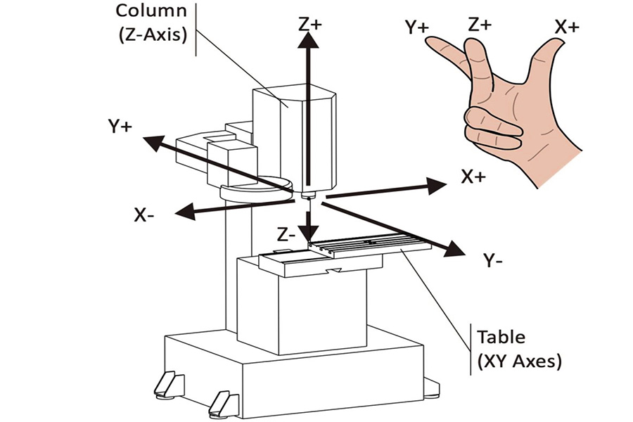
| Movement mode | The tool rotates, the workpiece is fixed to the worktable and moves | The workpiece rotates, and the tool moves axially or radially |
| Applicable shapes | Planes, slots, holes, complex 3D surfaces (such as molds) | Cylindrical, conical, threaded and other rotationally symmetrical features |
| Typical tool types | End mills, face mills, ball-end mills, T-slot mills | External turning tools, internal hole turning tools, thread turning tools, cut-off tools |
| Processing accuracy | ±0.005–0.02mm (special processes are required for high precision) | ±0.001–0.01mm (higher accuracy for rotating bodies) |
| Material applicability | Wide range (metals, plastics, composite materials, especially hard materials) | Ductile materials (aluminum, copper, steel, brittle materials are prone to edge collapse) |
| Surface quality | Ra 0.4–3.2μm (depends on tool path optimization) | Ra 0.1–1.6μm (continuous cutting is easier to control) |
| Complexity | Can process polyhedrons and asymmetric complex structures | Suitable for axisymmetric parts, complex structures require multi-axis turning centers |
| Production efficiency | Medium-low (frequent tool changes, multiple processes) | High (continuous cutting, suitable for mass production) |
| Typical application scenarios | Mold cavities, mobile phone housings, aviation structural parts | Shaft parts, flanges, threaded fasteners |
| Equipment cost | High (multi-axis milling machines can reach millions) |
Low (standard lathe costs are about 200,000-500,000 yuan) |
Additional explanation
- Combined processing trends: Modern five-axis milling and turning centers can combine the advantages of both, such as processing complex parts such as impellers.
- Accuracy comparison: Turning has more advantages in controlling rotational symmetry tolerances such as cylindricity and roundness, while milling is more flexible in flatness and position.
- Tool wear: Milling causes faster tool wear due to intermittent cutting (about 30% higher than turning).
Summary
CNC milling needs to balance process, cost and quality with a systematic thinking. The core lies in achieving efficient machining through tool geometry optimization (such as rake angle, helix angle, coating matching material properties), machining strategy design (such as down milling vibration reduction, layered cutting to control residual height) and workpiece structure adaptation (such as wall thickness ≥ 0.8mm to prevent deformation, corner radius ≥ 130% tool diameter); at the same time, it is necessary to combine the machine tool performance boundaries (such as spindle power, dynamic accuracy) and fixture rigidity (vacuum/hydraulic fixture to reduce clamping deformation) to ensure stability, and finally achieve quality goals through tolerance grading (typical ± 0.025mm, limit ± 0.0125mm) and post-processing verification (such as white light interferometer to detect micron-level morphology), forming a full-link closed-loop optimization from design to manufacturing.

📞 Phone: +86 189 2585 8912
📧 Email: Doris.wu@js-rapid.com
🌐 Website: https://jsrpm.com/
Disclaimer
The content of this page is for informational purposes only.JS Series No representations or warranties of any kind, express or implied, are made as to the accuracy,completeness or validity of the information. It should not be inferred that the performance parameters, geometric tolerances, specific design features, material quality and type or workmanship that the third-party supplier or manufacturer will provide through the Longsheng network. This is the responsibility of the buyerAsk for a quote for partsto determine the specific requirements for these parts.please Contact us Learn more information.
JS Team
JS is an industry-leading companyFocus on custom manufacturing solutions. With over 20 years of experience serving more than 5,000 customers, we focus on high precisionCNC machining,Sheet metal fabrication,3D printing,Injection molding,metal stamping,and other one-stop manufacturing services.
Our factory is equipped with more than 100 state-of-the-art 5-axis machining centers and is ISO 9001:2015 certified. We provide fast,efficient and high-quality manufacturing solutions to customers in more than 150 countries around the world. Whether it’s low-volume production or mass customization,we can meet your needs with the fastest delivery within 24 hours. choose JS Technology It means choosing efficiency, quality and professionalism.
To learn more, please visit our website:jsrpm.com