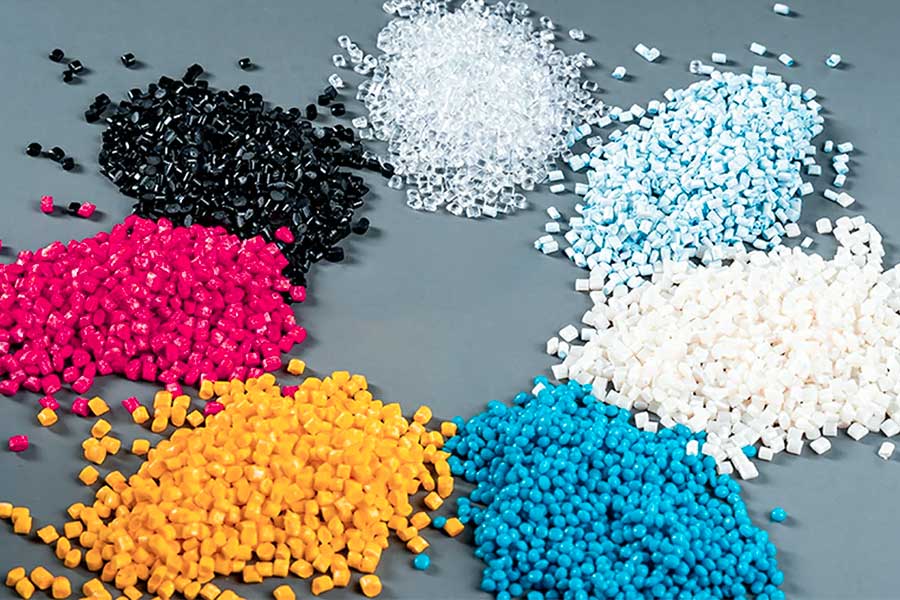
Injection molding is one of the core processes of modern manufacturing industry. It is widely used in automotive, medical, electronic and consumer goods. At its core, plastic or silicone materials are melted by heating, injected into a mold cavity under high pressure, cooled and solidified to form precise molding parts.
Based on the technical advantages of JS precision manufacturing, this paper summarizes the key success factors of injection molding from the design and engineering perspectives.
What are the engineering considerations in the design phase of injection molding?
1.Wall thickness design
Wall thickness should be uniform (1-4mm recommended) to avoid shrinkage marks or warping caused by uneven molding injection pressure. For example, JS company optimized the wall thickness gradient by mold flow analysis and controlled tolerance within ±0.05mm.
Thick areas require to be designed with weight-reducing ribs (such as honeycomb structures) to reduce cooling time and improve the structural strength of injection molding parts.
2.Meeting the demolding requirements
External surface slope ≥0.5℃, inner pore or slider structure ≥2℃ to ensure smooth demolding after molding injection. JS optimised the slope design of the car components to demolding efficiency efficiency by 40%.
3.Optimizing the flow path of the melt
According to the injection-molding characteristics, choose side door, pinpoint door or heat flow system. JS, for example, can reduce cold-end waste by up to 30% by using heat channels to make sophisticated electronic components.
The position of the gate should avoid external view, balance the filling of the multi-cavity die and avoid the influence of weld on strength.
4.Relationship between material characteristics and mold design
Crystalline materials (such as PA66) have a shrinkage rate up to 2% and require size correction through a mold compensation factor (usually 0.5-1.5%). JS's model flow analysis software predicts shrinkage error ≤0.2%.
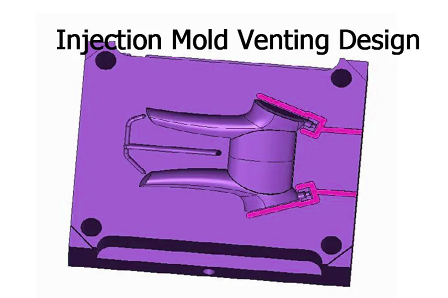
5.Mold exhaust
Exhaust grooves (depth 0.02-0.04mm) are designed on the parting surface or at the top pin to prevent gas entrapment due to melting pressure during molding injection. The efficiency of JS exhaust is improved by 25% by vacuum assisted exhaust technology.
6.Strengthening reinforcement and support
The recommended reinforcement thickness is 0.6 times the thickness of the wall and the spacing ≥2 times the thickness of the wall, thus satisfying load bearing requirements and avoiding shrinkage risk.
7.Classification surface design
Type lines should be hidden from sight and coincide with the opening and closing direction of injection mold. For example, JS develops sliding parting structures for consumer electronics components to prevent flybys.
8.Embedded components and local reinforcements
The metal inserts are required to be preheated (e.g. 120-150 ℃) in order to stop temperature difference-related stress cracking under injection moulding. JS's patented embedded positioning system can put the offset in position to ±0.1mm.
How to choose thermoplastic materials in injection molding engineering?
1.Positioning by function: Material type based on performance needs
- Mechanical strength: For automobile bumpers that require impact resistance, the optimum PC/ABS alloy offers high toughness of PC and flowability of ABS, suitable for complex plastic molding processes.
- Temperature resistance: Electronic connectors have to withstand welding temperature, PA46 with 295 °C melting point is better than PA66, and a crystallization rate is suitable for high-speed forming processes.
2.Process adjustment: Compatibility of material properties with injection molding conditions
Liquidity Classification:
- Low viscosity materials (e.g. PP): Suitable for thin-walled plastics molding components, the mold gates can be reduced in size.
- High viscosity materials (e.g. PET): High injection pressure demands, widely applied to precision components such as gear injection molding.
Shrinkage control:
Crystalline plastics such as PA and PBT will shrinkage rate by 2%-3% and require mold compensation design to compensate for deformation, the plastic molding accuracy relies heavily on which is critical.
3.Cost balance: material cost-effectiveness and mass production demands
ABS: Balanced and comprehensive, widely used in household appliance casings (15% of global plastic usage), suitable for small and medium sized custom processing.
PP: Low density (0.9g/cm), lower unit cost than engineering plastics, commonly used in car interiors (e.g. door panels).
4.Exceptional circumstances: a Material breakthrough in extreme working conditions
- Chemical resistance: Medical devices require access to disinfectant. PPSU has strong oxidation resistance, stable melt viscosity and is suitable for plastic molding environments of clean room.
- Biocompatibility: Insulin pen ingredients must be ISO 10993 tested, there is no risk of COC precipitation, and low water absorption ensures long-term storage stability.
5.Green materials and circular economy
Biobased materials:
- Polylactic Acid: The degradation cycle is controlled, but injection molding temperature (170-200°C) need to be optimized to avoid warping and make it suitable for packaged fast consumer goods.
- PHA (polyhydroxylalkylate): Biodegradable in the ocean, but with low melting strength, requires the addition of a 20% fiberglass reinforcement for ocean buoys.
Regeneration cycle:
RPET: It needs to be dried to less than 0.02% moisture content. Its crystallization rate is slow and the shelf life needs to be extended in order to increase the plastic molding output.
Influence of mold exhaust design on injection quality?
Mold exhaust design directly affects the output and performance of the product. Reasonable exhaust system can optimize melt flow, reduce defects and improve production efficiency. The following are specific impact and optimization strategies:
1.Reduction of trapped gases and combustion defects
- During injection molding, the molten material fills the mold cavity at high speed. If the exhaust is not smooth, it is easy to produce gas retention, resulting in surface burning or internal porosity of products.
- Exhaust design of the parting surface is key to molding design: Retention of exhaust grooves of 0.02-0.04mm, matched to gaps in the nozzle or slider, reduces the risk of trapping air by more than 80%.
2.Improve the appearance fusion line
- Melting line is a common problem in gate injection, and it is easy to produce appearance defects or strength weakness.
- Optimizing the exhaust path can guide the orderly flow of the melt and control the position of the melt line. For example, in a car mold of a headlight reflector, the yield increases to 98% by adjusting the direction of the exhaust trough to move the solder wire from the visible to the invisible surface.
3.Prevent warping
- Gas residue can cause uneven local cooling, causing the product to warp.
- In the molding design of deep cavity die, spiral or layered exhaust exhaust structure used to balance the pressure in the cavity, and the shrinkage rate difference difference is controlled to within 0.3%.
4. Improve surface smoothness
Poor exhaust can cause friction between the melt and air, thereby creating burrs or atomized patterns, which affect glossiness.
Mirror mold requires precise control of exhaust groove depth within 0.01mm, and an assist system of vacuum to achieve a super smooth surface with Ra ≤0.02μm.
5.Optimize production efficiency
- Poor exhaust can prolong the insulation time, leading to a longer cycle time.
- CAE simulation can shorten injection molding cycle by 10%-15%. Recently, JS has adopted a multi-point exhaust design in an household appliance panel mold project, achieving a 20% increase in daily production capacity.
What are the design standards for the depth of the mold exhaust groove?
The following are specific design points and requirements, as well as actual application conditions and types of plastic moldings needs:
1.Basic depth range and material modification
| Type of Material | Depth range of exhaust groove | Design highlights |
| Universal plastics (ABS/PP) | 0.02-0.04mm | Avoid melt overflow and adapt to conventional injection molding pressure. |
| High viscosity plastic (PC/POM) | 0.04-0.06mm | Compensation for flow resistance of high viscosity materials. |
| Transparent plastics (PMMA) | 0.01-0.03mm | Prevent exhaust traces from affecting optical performance. |
2.Process parameter and structure correlation
| Process conditions | Adjustment of exhaust groove depth | Plastic molding adaptation strategy |
| High pressure injection molding (>100MPa) | Deepen to 0.05-0.08mm | Cooperate with the heat flow system to reduce the risk of trapped gas. |
| Long holding time (>10 seconds) | Reduce to 0.02-0.03mm | Avoid gas backflow, causing shrinkage marks. |
| Fiber-reinforced materials (e.g. PA+GF) | 0.01-0.02mm | Prevent fiberglass from clogging the exhaust passage. |
3.Innovation direction and quality control
| Quality control objectives | Exhaust groove depth standard | Testing methods | JS optimization case |
| Prevention of combustion (surface defects) | ≥0.03mm | Flow analysis+surface roughness testing. | The burning rate of the shell mold of the mobile phone has been decreased from 5% to 0.5% by deepening the exhaust groove (0.04mm). |
| Improve surface smoothness | ≤0.02mm | Measurement instrument+visual inspection. | The optical lens mold utilizes laser engraved exhaust groove (0.015mm) with Ra ≤0.02 μm. |
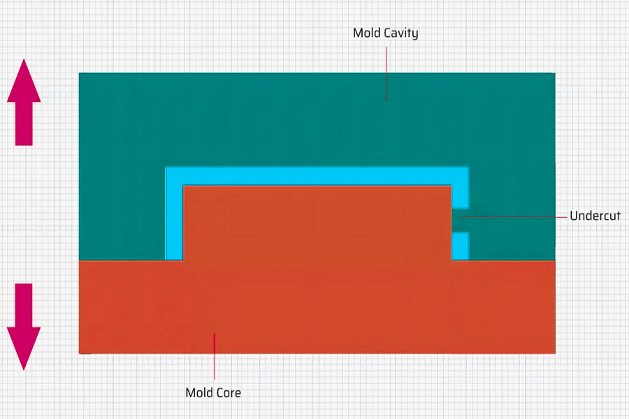
How to demold the inverted buckle structure when designing injection molded parts?
1.Slider demoulding technology
We use a sloping guide pin to displace the slider so as to achieve lateral demoulding. It uses a mechanical linkage mechanism to allow products with undercuts to be demoulded easily from the mould. The angle of the sloping guide pin should be kept between 5-15° by the engineers. Such a range of angles can ensure the whole demoulding process is reliable and smooth.
In practical application, we have encountered demoulding problems for silicone molding. In order to resolve this problem, we sprayed a thin layer of PTFE coating on the surface of the slider. The material can successfully reduce silicone's adhesion. Taking the example of the case we developed for a medical client, by designing a system of multiple sliders working together in sync with each other, demoulding force was ultimately reduced by nearly one-third.
2.Sloped ejector demoulding technology
We use a sloping ejector rod in combination with an ejector pin system to complete demoulding. The mechanism releases the undercut structure from the mold through a tilting action. Designers must define the angle of the sloping ejector according to the material characteristics. For example, when dealing with elastic products such as silicone, it is recommended that one uses a sloping ejector angle of more than 7°, which has the effect of not stretching the product during demoulding.
In actual injection molding production, we have developed a segmented sloping ejector solution for TPU materials with high elasticity. The improvement reduces the moving distance when demoulding to only 2mm. For example, with the automotive silicone button mold that we developed, after applying this sloping ejector demoulding system, even small and precise structures can be demoulded perfectly.
3.Hydraulic-assisted demoulding technology
The external motion mechanism of the mold is driven by the hydraulic system. It is particularly suitable for the processing of large size or deep cavity structure products. The hydraulic cylinder is used as the power source and has the ability to provide stable demoulding force.
In design, two hydraulic cylinders are typically designed to work together so that the demoulding forces at both sides of the mould can be completely synchronized. We have implemented this system on one specific car accessory. The coordinated working of the two cylinders makes the entire demoulding process more stable and reliable, thereby in essence eliminating the problem of product deformation.
4.Bending pin demoulding technology
We take a bending pin mechanism to eliminate the demoulding problem of shallow undercut structures. At mold opening, the bending pin will bend as a lever to drag the undercut component out from the product. In order to prevent the soft rubber material adhering to the bending pin, we will spray Teflon anti-stick coating on the bending pin's surface.
In production practice, we have particularly designed an electric silicone gasket mold with bending pin of spring reset system. In several test trial rounds, we determined that adjusting the bending pin's angle would significantly reduce demoulding resistance. Finally, with this upgrading plan, there is 20% greater efficiency in production.
5.In-mold hot cutting demolding technology
We apply a heat blade that cuts the product connection to the runner directly in the mold. The system demands accurate control of the temperature of the blade, usually set between 200 and 300℃. At low temperature, it will not cut, while at high temperature, it will readily burn the material.
For example, when we made the mold of the silicone watch strap, we used this hot cutting technology with a robot to absorb the pieces. Compared with traditional technologies, this system does not need the following trimming step and saves the factory directly 15% of the cost of production.
What are the requirements for reinforcing rib layout when designing injection molded parts?
1.Ratio of wall thickness to reinforcement thickness
- Reinforced tendons are typically 0.5-0.7 times thicker than the product wall to avoid shrinkage marks or uneven cooling due to sudden changes in wall thickness.
- Plastics molding adaptations: In thin-walled components (e.g. electronics casings), the thickness of the ribs needs to be thinner (e.g., 0.3-0.4mm) to prevent excessive resistance to melt flow.
2.Layout direction and logistics
- Flow matching: Reinforcement should be arranged along the flow direction of the injection molten mass to reduce flow resistance and avoid gas retention.
- In complex structures, such as car dashboards, the ribs form 45° to the runways, balancing filling efficiency and structural strength.
3.Spacing and heat dissipation design
- Spacing standard: Steel bars should be spaced twice as thick to ensure uniform cooling and prevent local overheating deformation.
- Specific operation: In high precision plastic molding components such as connectors, too small rib spacing will lead to poor die exhaust, which needs to be optimized through CAE simulation.
4.Root demolding angle
- Slope requirement: The root of the reinforcing strip should be designed with a demolding slope of ≥0.5° to avoid damaging the product during demolding.
- Process adaptation: The rib roots of deep cavity components (such as home appliance liners) need to adopt a gradual slope to prevent mold exhaust blockage.
5.Avoid stress concentration
- Rounded corner transition: R angle ≥0.3mm at rebar joints to reduce stress concentration and improve fatigue resistance.
- Condition: Using plastics molding tool handles, ribs without rounded corners are prone to cracking due to assembly stress, and JS optimization to extend their lifespan by 50%.
Why choose JS to process injection molded parts?
1.Ultra-high precision guarantee
±0.005mm tolerances, precision control of hair wire diameter, guarantee that injection molding fully meets assembly requirements, and reduce later maintenance costs.
2.Rapid delivery capability
Industry leader 1-2 weeks fast delivery, to help you get a head start on the market, especially for emergency orders.
3.Complete Material Solutions
Covering more than 50 specialty plastics (such as PA66, POM, PC, etc.), customizable options from conventional materials to high temperature/ corrosion resistant materials are available to meet the requirements of different areas.
4.Cost optimization black technology
The original process reduces production costs by 20% and can help you achieve higher quality on the same budget through smart scheduling and improved material utilization.
5.Professional escort throughout the whole process
Our 20-year experienced engineers provide complete mature service from design optimization to trial mold debugging. The high complexity structural parts achievement rate is over 95%, significantly shortening the research and development cycle.
Summary
Injection molding not only is an application of the practice of material science, but also is deeply the combination of precision machinery engineering and digitalization. JS Precision Manufacturing takes ±0.005mm machining tolerance as the central point, deeply combines molding concept with smart manufacturing technology, and builds a cross-industry database of materials and automated process matrix.
Within 20 years of technological accretion, we supported more than 300 businesses to transcend design barriers and skip-ahead their way from concept to volume manufacturing.

Disclaimer
The content on this page is for general reference only. JS Series makes no express or implied warranties regarding the accuracy, timeliness, or applicability of the information provided. Users should not assume that the product specifications, technical parameters, performance indicators, or quality commitments of third-party suppliers are completely consistent with the content displayed on this platform. The specific design feature, material standards, and process requirements of the product should be based on the actual order agreement. It is recommended that the purchaser proactively request a formal quotation and verify product details before the transaction. For further confirmation, please contact our customer service team for professional support.
JS Team
JS is an industry leading provider of customized manufacturing services, dedicated to providing customers with high-precision and high-efficiency one-stop manufacturing solutions. With over 20 years of industry experience, we have successfully provided professional CNC machining, sheet metal manufacturing, 3D printing, injection molding, metal stamping and other services to more than 5000 enterprises, covering multiple fields such as aerospace, medical, automotive, electronics, etc.
We have a modern factory certified with ISO 9001:2015, equipped with over 100 advanced five axis machining centers to ensure that every product meets the highest quality standards. Our service network covers over 150 countries worldwide, providing 24-hour rapid response for both small-scale trial production and large-scale production, ensuring efficient progress of your project.
Choosing JS Team means choosing manufacturing partners with excellent quality, precise delivery, and trustworthiness.
For more information, please visit the official website: jsrpm.com
FAQs
1.Injection molding process works in what way?
Injection molding melts plastic into a molten form, inserts it into a high-pressure precision mold, and freezes and solidifies. The mold is opened to remove the finished part. It is widely applied in the automotive, electronics, medical and other fields.
2.How to position the best gate position?
The best gate position has to find a compromise between melt flow balance, shrinkage, appearance quality and exhaust efficiency. It is usually selected at the maximum wall thickness or distant from the key assembly surface, supplemented by mold flow analysis and optimization.
3.What are the consequences of poor demolding angle?
Insufficient demolding angle will lead to product sticking, surface damage, dimensional deviation, and increased repair cost. JS can completely remove such defects through precision mold design optimization.
4.What are the signs of inadequate injection pressure?
Inadequate injection pressure will lead to incomplete filling of the product, rough surface, and highly visible weld lines, which will reduce the strength and appearance quality of the injection molded parts.
Resources
Injection molding of liquid silicone rubber